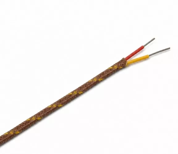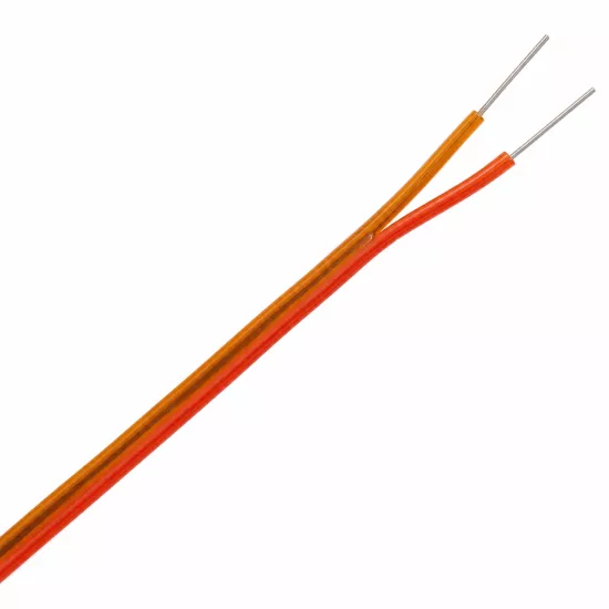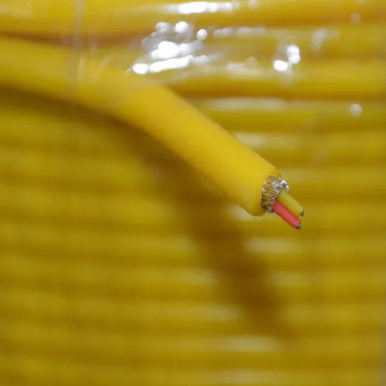
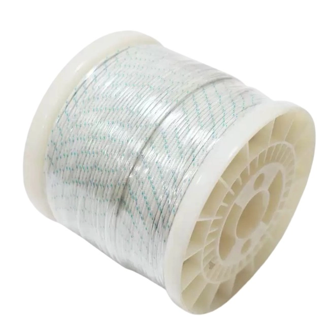
K-Type Ultra-Thin Fiberglass-Insulated Thermocouple Cable 2x0.10 mm is a thin temperature measurement cable used in K-Type thermocouple applications that require low thermal mass, installation in confined spaces, and monitoring of rapid temperature changes.
The cable consists of two ultra-thin thermoelement conductors and fiberglass insulation surrounding them. The diameter of each conductor is Ø0.10 mm . The thin conductor structure helps the cable respond to temperature changes at the measurement point with lower thermal mass.
The designation 2x0.10 mm means that both conductors are 0.10 mm in diameter. This value is not the conductor cross-sectional area; therefore, the product must not be interpreted as 2x0.10 mm² for its cross-sectional area.
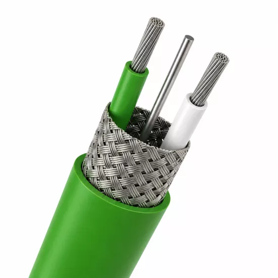
The cable is not shielded; it has no metal braid, foil shield, or drain wire. In applications with high levels of electrical interference, the cable route must be separated from power cables, or a suitable shielded thermocouple cable should be considered.
The Ø0.10 mm thermoelements have a lower thermal mass than standard-cross-section thermocouple cables. This construction is beneficial in applications that monitor small parts, thin surfaces, and rapid temperature changes.
The thin cable construction facilitates routing through narrow channels, small sensor bodies, and confined installation spaces. It also helps create a smaller measurement connection in laboratory setups, electronic components, and precision-testing applications.
Ultra-thin conductors are more mechanically sensitive than thick cables. The cable must be protected from pulling, hard bending, crushing and repetitive motion loads. It is recommended that the connection points be fixed so that they do not carry mechanical load.
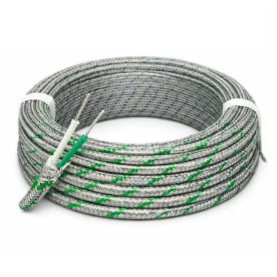
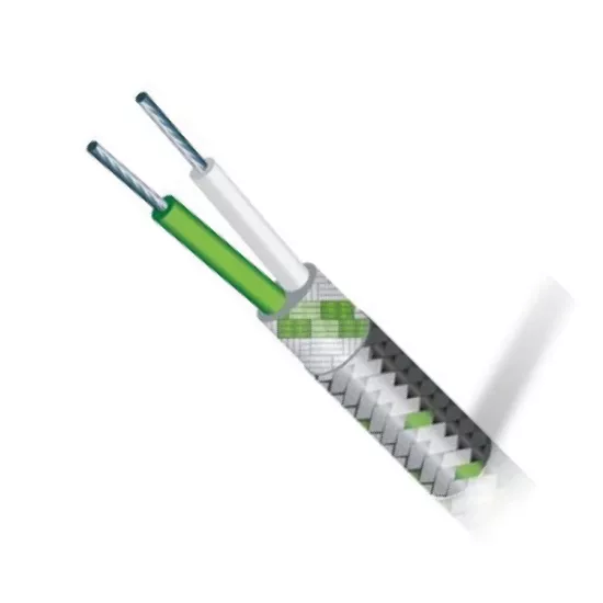
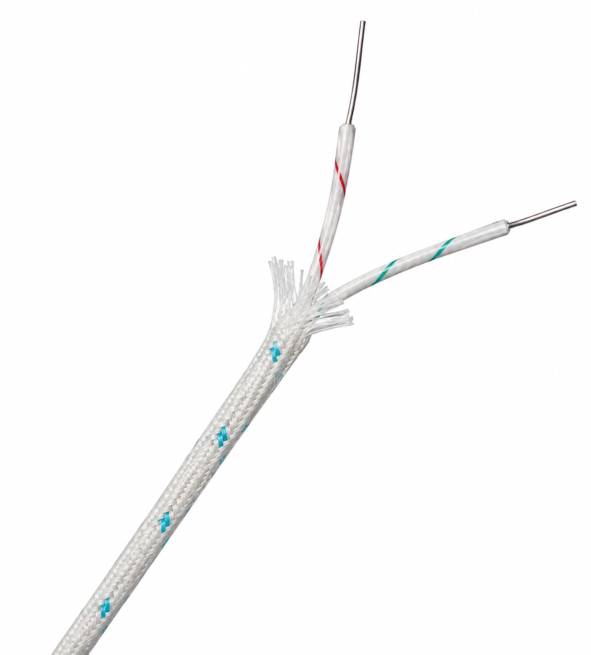
The measurement conductors are separated from each other by fiberglass braid insulation. The fiberglass structure creates a thin and flexible insulation layer for thermocouple cables used in high-temperature measurement environments.
There is also a fiberglass braid structure in the outer section. This braid holds the inner conductors together and provides basic physical protection. However, it should not be used in place of metal armor or heavy-duty mechanical protection.
Fiberglass braid is not a liquid-tight outer sheath. The cable should be additionally protected in applications where oil, intense humidity, chemical splashes, sharp edges and abrasive surfaces are present.
| Cable Component | Structure | Function |
|---|---|---|
| Positive thermoelement | Ø0.10 mm ultra-thin conductor | Forms the positive side of the K-Type thermocouple measurement circuit. |
| Negative thermoelement | Ø0.10 mm ultra-thin conductor | Forms the negative side of the K-Type thermocouple measurement circuit. |
| Core insulation | Fiberglass braid | It electrically separates positive and negative conductors. |
| Outer construction | Fiberglass braid | It holds two cores together and provides basic physical protection. |
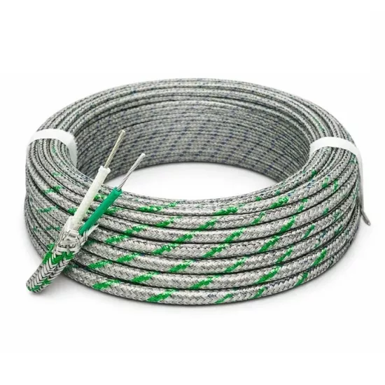
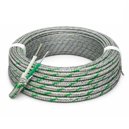
The positive and negative conductors in the cable can be distinguished by the manufacturer with colored threads, lines or insulation markings. In the product image, there are different colored markings on the cores.
During connection, no action should be taken based solely on visual color. The manufacturer's polarity definition, product label and positive-negative terminal markings of the device to be used should be checked together.
Different manufacturers may use IEC, ANSI, JIS, or manufacturer-specific color markings. A different color scheme alone does not change the thermocouple type; the essential requirements are that the cable be suitable for the K-Type measurement circuit and that polarity be maintained correctly.
The seller's technical table specifies a temperature range of -200°C to +500°C for the product.
This value is not further classified as continuous operating temperature, short-term usage temperature or only thermoelement measurement limit. For this reason, especially in applications close to temperature limits, the manufacturer's technical documentation and actual installation conditions should be used as the basis.
The temperature resistance of the connection terminal, connector, joint material, and mounting components may be lower than that of the cable itself. All connection components must be considered when determining the system's usable temperature limit.
The thin conductor diameter reduces the amount of metal that needs to be heated or cooled at the measurement point. For this reason, it can help to respond faster to temperature changes in applications where the cable is used with the appropriate measurement junction.
The actual response time depends on the measuring-junction construction, weld or junction size, contact between the sensor and surface, airflow, and installation method. An exact response time must not be specified based solely on conductor diameter.
The positive and negative thermoelements must be connected to the corresponding positive (+) and negative (-) terminals of the K-Type temperature controller. Reverse polarity may cause the temperature change to be displayed in the wrong direction.
Ultra-thin conductors can break more easily than standard cables. Low mechanical force should be applied when stripping the cable ends, connecting them to a terminal, or preparing the measuring junction.
The conductor ends should not bear the weight of the cable at the connection point. The cable must be supported by a suitable clamp, fixing element or strain relief structure.
The cable should not be used directly on routes where there is constant movement, vibration or friction. In mobile applications, mechanical protection and appropriate fixing method should be evaluated.
The fiberglass construction is not a substitute for a protective outer sheath against open flame, molten material, chemical splashes, or water ingress. The environmental conditions must also be evaluated before use.
This product is not a power-supply cable. It must not be used to power a motor, heating element, heater, or any other electrical load.
Although the cable has a thermoelement construction, its thermocouple tolerance class, calibration suitability, and the manufacturer's intended-use description must be checked before making a sensor measuring junction.
If the product is classified only for connection or extension use, its cores must not be joined to form a measuring junction. Before manufacturing a sensor, the manufacturer's documentation must confirm that the product can be used as a thermocouple element.
When choosing a cable, thermocouple type, conductor diameter, required response speed, ambient temperature, mechanical strength, humidity, chemical contact and the device to be connected should be evaluated together.
If rapid response and a small measurement point are priorities, an Ø0.10 mm ultra-thin conductor may be preferred. Ø0.20 mm, Ø0.30 mm, or thicker thermoelement options should be considered for applications requiring greater mechanical strength.
In environments with electrical interference, a shielded cable may be required, or the measurement circuit may need to be separated from power cables. This product has no shield or drain wire.
It indicates that the cable has two conductors, each 0.10 mm in diameter. This value is the conductor diameter, not the cross-sectional area.
No. The manufacturer's information refers to two Ø0.10 mm diameter conductors. The calculated geometric area of each conductor is approximately 0.00785 mm².
The low thermal mass helps provide a faster response to temperature changes when the measuring junction and installation conditions are suitable. It also provides a more compact construction for small parts and confined installation spaces.
Ø0.10 mm conductors are mechanically more delicate than thicker thermocouple wires. They must be protected from tension, sharp bending, vibration, and terminal loads.
The core insulation and outer braid are made of fiberglass.
The seller's technical table gives a temperature range of -200°C to +500°C. Because it does not state whether this is a continuous or short-term operating range, the manufacturer's technical documentation must be used as the basis.
No. The product has fiberglass-braid insulation but no metal braided shield or drain wire for electrical shielding.
No. The fiberglass braid provides electrical insulation and basic physical protection. The metal braided shield is a conductive layer used to reduce the effect of electrical interference.
No. The product is used for a low-level K-Type thermocouple measurement signal. It must not be used to power electrical loads.
The manufacturer's technical documentation for the K-H-GGF model should be used as the basis for the exact thermoelement alloys, tolerance class, calibration suitability, continuous operating temperature, electrical resistance value and minimum bending radius of the product. Values specified by the seller but not explained in the usage method should not be considered the exact application limit of the product.




 EN
EN Türkçe